

Two Roads From Green Hydrogen to Liquid Fuel: Hy2Market Compares Fischer-Tropsch and Methanol-to-Jet
Hy2Market project partner ProzessOptimal has completed a detailed process-engineering comparison of two established routes for converting green hydrogen and captured CO₂ into synthetic liquid fuels: the Fischer-Tropsch pathway and the Methanol-to-Jet pathway. Built as full-scale process simulations sharing a common front end, the study gives the consortium and the wider e-fuels sector a like-for-like view of how the two routes compare on efficiency, product output, and operational complexity.
The work sits within Work Package 4, which examines industrial pathways for putting green hydrogen to use beyond direct injection or combustion. Fischer-Tropsch and Methanol-to-Jet are the two routes most commonly discussed for producing sustainable aviation and marine fuel from hydrogen and captured carbon, yet they differ substantially in how they get there — which is exactly what this comparison set out to quantify.
A Shared Starting Point
Both simulated processes begin from the same place: a large-scale PEM electrolyser producing green hydrogen, paired with an amine-based scrubber that captures CO₂ from an industrial flue gas stream. From there, both hydrogen and CO₂ are compressed and distributed to their respective synthesis routes. Using a shared, identically modeled front end means any differences that show up further downstream can be attributed to the synthesis routes themselves, rather than to how the hydrogen or carbon dioxide was produced.
Two Different Ways to Build a Fuel Molecule
The Fischer-Tropsch route takes the more direct path. Hydrogen and CO₂ are converted to synthesis gas and then built up into a broad spread of hydrocarbon chains in a single catalytic reactor system, following the well-known Anderson-Schulz-Flory distribution. The resulting mixture is then upgraded and cracked down into usable fuel fractions.
The Methanol-to-Jet route takes a longer, more sequential path. Hydrogen and CO₂ are first combined into methanol, which is then converted into light olefins, built up into longer kerosene-range molecules through an oligomerization step, and finally stabilized by hydrotreating. A steam-reforming step recovers carbon and hydrogen from process off-gas and feeds it back into the loop, rather than letting it go to waste as fuel gas.
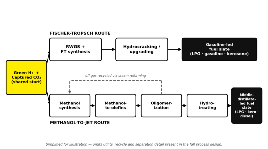
Figure 1: Both routes begin from the same green hydrogen and captured CO₂ feed. The Fischer-Tropsch route (top) runs it through combined RWGS/FT synthesis and hydrocracking to a gasoline-led slate; the Methanol-to-Jet route (bottom) runs it through methanol synthesis, methanol-to-olefins, oligomerization and hydrotreating to a middle-distillate-led slate, with off-gas recycled back into the loop via steam reforming.
Efficiency and Carbon Retention
For a comparable hydrogen input and a similar electricity draw, the Methanol-to-Jet route came out ahead on both counts that matter most for a producer: it converted a meaningfully higher share of the input energy into finished liquid fuel, and it retained a clearly larger share of the input carbon in the final products rather than losing it to process heating or purge streams. The gap traces back to the same design choice — recycling by-product gas through a steam reformer rather than burning it — which lets the Methanol-to-Jet route claw back carbon and hydrogen that the Fischer-Tropsch configuration, as modeled, sends to internal process heating instead.
A Tale of Two Product Slates
The two routes also diverge sharply in what they actually produce. The Fischer-Tropsch route, true to its broad-spectrum reaction chemistry, comes out gasoline-led, with kerosene as a substantial secondary fraction. The Methanol-to-Jet route is weighted the other way: it is a middle-distillate-led process, producing kerosene and diesel as the dominant fractions and comfortably out-producing the Fischer-Tropsch route on combined middle-distillate output.
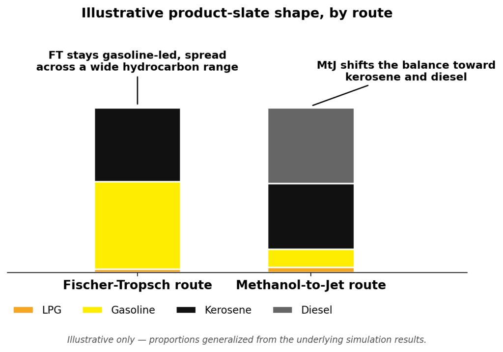
Figure 2: Stacked comparison of each route’s output mix — LPG, gasoline, kerosene and diesel — showing the Fischer-Tropsch route’s gasoline-led shape against the Methanol-to-Jet route’s middle-distillate-led shape.
For a project focused on decarbonizing aviation and maritime transport, that distinction matters. Where kerosene and diesel are the target products, the Methanol-to-Jet route’s middle-distillate-heavy slate is the closer fit; where a broader liquid-fuel output is acceptable, the Fischer-Tropsch route’s gasoline-led spread remains a well-proven option.
Complexity and Flexibility Trade-offs
Neither route is simply “better” in an absolute sense — each carries its own engineering trade-offs. The Fischer-Tropsch route needs fewer reactor stages overall, but relies on a hydrocracker and a more intricate gas-recycle system to keep unwanted methane formation under control. The Methanol-to-Jet route involves more sequential conversion steps and continuous catalyst regeneration in its olefins reactor, but gains a practical advantage in return: methanol is a stable, storable, transportable intermediate. That means electrolysis and fuel synthesis can, in principle, be decoupled in time — useful in a system where renewable electricity supply fluctuates — and it opens the option of selling methanol directly as a chemical feedstock when fuel demand is soft.
What Comes Next
This comparison feeds directly into Work Package 4’s ongoing work on industrial hydrogen use cases, giving project partners and prospective e-fuel producers an evidence-based starting point for route selection rather than a choice made on reputation or precedent alone. The full engineering report, along with the project’s other Work Package 4 outputs, is being prepared for release through the usual Hy2Market project channels.